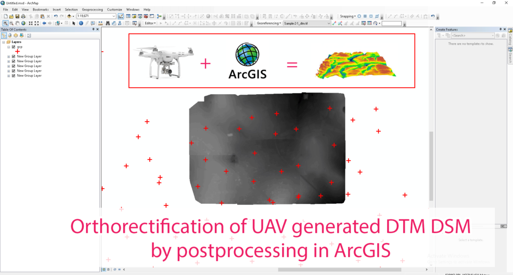
Summary – Orthorectification of UAV generated DTM DSM by postprocessing in ArcGIS.
Orthorectification of UAV generated DTM DSM by postprocessing in ArcGIS, it requires DTM or DSM generated from PIX4d or Agisoft (any photogrammetry software) and GCPs to rectify data from.
Two Steps:
- Finding error between GCP elevation and our Elevation Model (DSM or DTM file) values.
- Rectifying the Elevation Model by adjusting the interpolated error surface.
The Problem
Problem
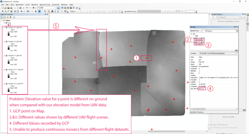
Problem: Elevation value for a point is different on ground when compared with our elevation model from UAV data.
- GCP point on Map.
- (2.&3.) Different values shown by different UAV flight scenes.
- (4.) Different Values recorded by GCP.
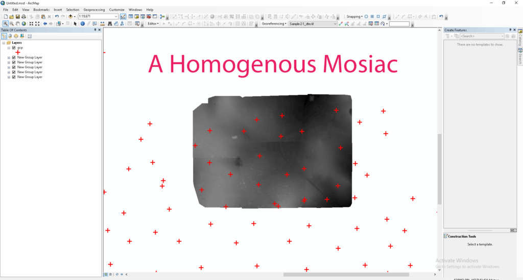
- Unable to produce continuous mosaics from different flight data sets.
Procedure
Finding error between GCP elevation and our Elevation Model (DSM or DTM file) values
Select GCP points over the Elevation Model file
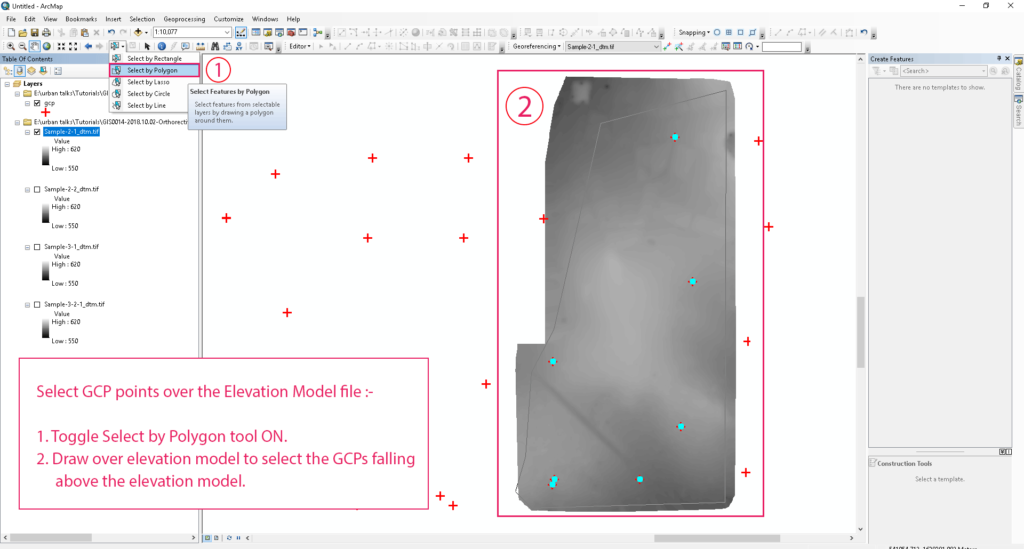
Select GCP points over the Elevation Model file:
- Toggle Select by Polygon tool ON.
- Draw over elevation model to select the GCPs falling above the elevation model.
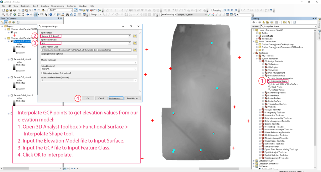
Interpolate GCP points to get elevation values from our elevation model
Interpolate GCP points to get elevation values from our elevation model :
- Open 3D Analyst Toolbox > Functional Surface > Interpolate Shape tool.
- Input the Elevation Model file to Input Surface.
- Input the GCP file to Input Feature Class.
- Click OK to interpolate.
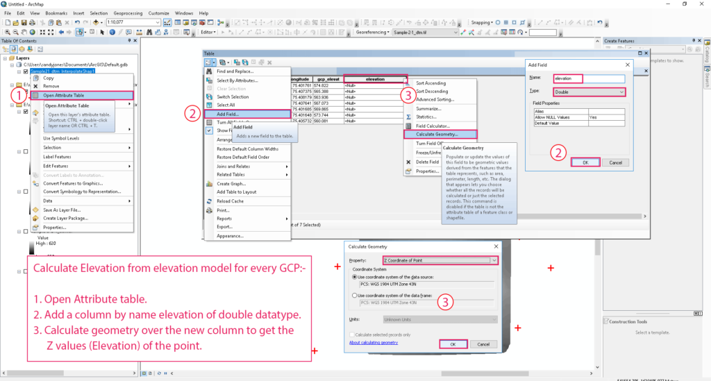
Calculate Elevation from elevation model for every GCP
Calculate Elevation from elevation model for every GCP :
- Open Attribute table.
- Add a column by name elevation of double datatype.
- Calculate geometry over the new column to get the Z values (Elevation) of the point.
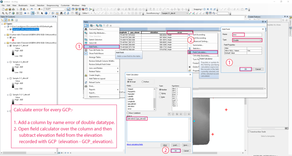
Calculate error for every GCP
Calculate error for every GCP :
- Add a column by name error of double datatype.
- Open field calculator over the column and then subtract elevation field from the elevation recorded with GCP (elevation – GCP_elevation).
Rectifying the Elevation Model by adjusting the interpolated error surface
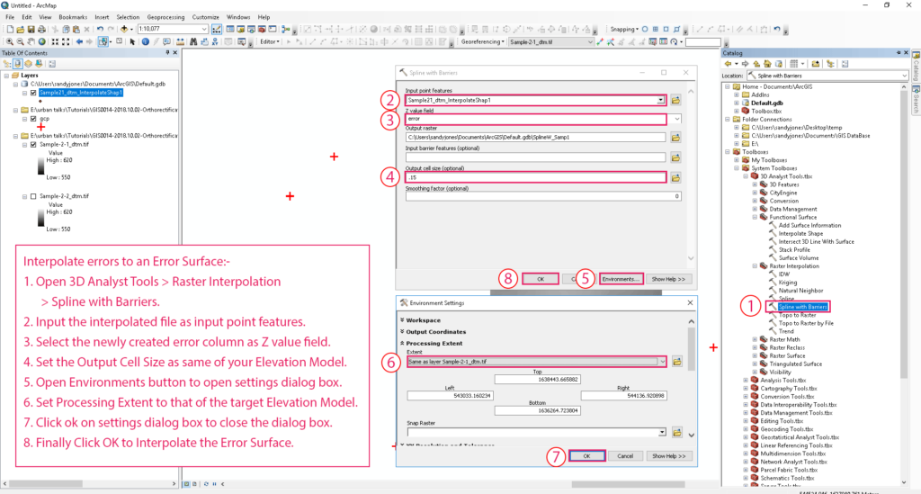
Interpolate errors to an Error Surface
Interpolate errors to an Error Surface:
- Open 3D Analyst Tools > Raster Interpolation > Spline with Barriers.
- Input the interpolated file as input point features.
- Select the newly created error column as Z value field.
- Set the Output Cell Size as same of your Elevation Model.
- Open Environments button to open settings dialog box.
- Set Processing Extent to that of the target Elevation Model.
- Click ok on settings dialog box to close the dialog box.
- Finally Click OK to Interpolate the Error Surface.
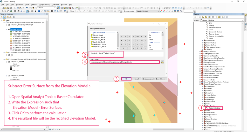 Subtract Error Surface from the Elevation Model
Subtract Error Surface from the Elevation Model :
- Open Spatial Analyst Tools > Raster Calculator.
- Write the Expression such that Elevation Model – Error Surface.
- Click OK to perform the calculation.
- The resultant file will be the rectified Elevation Model.
Tadda done!!
Result
Feature Image
if you like the tutorial please spread the word aand comment below if you have any questions.